Understanding the “How To” of providing appropriate lubrication for fixed or mobile plant and machinery is extremely important for acceptable machinery reliability and the economic success of the machinery owners.
An understanding the actual clearance size (Thickness-Depth) of the different types of lubrication films formed between machinery’s rolling, rotating and sliding components is essential for the task of providing good lubrication to become a little easier to complete. The measuring units used for measuring the minute sizes of oil film thickness in machinery are microns (µm), or one millionth of a meter.

The example in the above electron microscope image is a human hair, human hairs are sized 70-100 µm or 0.003-0.004 of an inch, (0.001 of an inch = 25 µm)
The lower limit of human vision is 40 µm or about half the human hair image.
The lower limit of human feel sensitivity, finger tip touch, is 15 µm or 0.0005 of an inch (About a quarter to one third of the human hair image.)
The Black Image Border is proportionally equivalent to 1 µm which is larger than the majority of the lubrication film thickness’s established in the normal types of mechanical applications encountered in the chart below.
Normal Lubrication Film Clearances formed in Applications when Operating.
| Human Hair | 70 to 100 µm |
| Limit of Human eyesight | 40 to 50 µm |
| Roller Bearings | 0.4 to 1 µm |
| Ball Bearings | 0.4 to 0.7 µm |
| Journal Bearings | 0.5 to 25 µm |
| Hydrostatic Bearings | 5 to 100 µm |
| Gears | 0.1 to 1 µm |
| Dynamic Seal | 0.05 to 0.5 µm |
| Gear Pump, Tooth to side plate | 0.5 to 5 µm |
| Gear Pump, Tooth tip to case | 0.5 to 5 µm |
| Vane Pump, Sides | 5 to 13 µm |
| Vane Pump, tip | 0.5 to 1 µm |
| Hydraulic Piston Pump, piston to bore | 5 to 40 µm |
| Hydraulic Piston Pump, Valve plate to cylinder | 0.5 to 5 µm |
| Hydraulic Servo Valves, Orifice | 130 to 450 µm |
| Hydraulic Servo Valves, Flapper Wall | 18 to 63 µm |
| Hydraulic Servo Valves, Spool to Sleeve | 1 to 4 µm |
| Hydraulic Actuators | 130 to 450 µm |
One inch = 25.4 millimetres (25,400 µm), 1 µm = 0.00003937 inch, 0.001 Inch (One Thou’) = 25 µm
There are some applications that form thicker oil films like journal bearings and hydrostatic (Pressurised) bearings in reciprocating combustion engines, (Big end or main bearings in your car). But in the majority of these applications there still remains instances of tight clearance oil films like rockers to cam lobes, piston rings to bore in engines and oiling rings sliding on shafts in journal bearings that run at < 1 µm lubrication film clearance.
This lubrication film thickness information impacts on the usual way lubrication maintenance is approached as without understanding the lubrication film clearance provided it will only be the visible dirt and debris contaminates that are prevented from entry and not the contaminates that are sized less than the human vision limit.
The R&T Lab’s Reliability Work indicates fine hard airborne environmental contamination sized 2-20 µm causes 80-90% of abnormal wear in oil and grease lubricated plant and machinery in the industrial plants we examine.
Most Frequent Ingress Points for Contamination into Different Machine Applications
With Combustion Engine, Compressor and Blower Type Applications, the usual fine dirt ingress contamination path is through the air cleaner and on down into the Oil Sump or Oil Reservoir Systems .
With Gear Drive, Transmission, Differential, Pump and Hydraulic Applications, the usual contamination entry point is via the Air Breather (Atmospheric Pressure Equalisation) Vents.
With Grease systems the usual contamination path is caused by pulse type grease relubricating methods in contaminated environments allowing dirt into the lubricated area because of the void left as grease is channelled away from the loaded areas between regreasing intervals.

The above chart (from Noria) indicates the distance and time these fine particles are able to remain suspended on the normal air flow. The most damaging sizes of hard contaminating particles are the 2-20 µm medium Mesoscale size range. (Below Limit of Human Vision) The finer end of the chart, Medium Mesoscale to Fine Microscale encompasses to normal lubrication film thickness, and as the chart indicates even the larger end of the chart can stay suspended on the air flow for a kilometer or more indicating this type of environmental contamination will be continual and should be always expected to be present even though there is no visual indication large enough for unaided human eyes to detect, to summarise;
The lubrication film thickness formed in the majority of machinery will not provide enough film thickness to be able to protect the application if normal airborne dirt carried in on the environmental air flow is permitted to have unfiltered access into engines, compressors and hydraulics. If unfiltered environmental air flow is permitted into the lubricated areas of gear drives, and transmissions serious wear will result as the majority of these applications have no oil filters with the fine dirt continually circulated around continually damaging the application.
Environmental Contamination of Engines, Compressors & Blowers
With engines, compressors and blowers, if the filtration is designed to suit the environmental conditions encountered and the filter servicing frequency is increased to prevent over loading the filters most well designed systems will cope reasonably OK.
When monitoring the air induction type applications (Blowers Compressors Engines) the lubricant’s Particle Count, Viscosity, PQ and TAN require to be monitored at an interval that allows any changes to above to be visually investigated by Ferrogram or Wear Debris Analysis to ensure no destructive abnormal wear modes have developed damaging the application before the next monitoring sample has been taken.
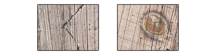
Visual examples here indicate the piston rings from a 60 ft Patrol Boat working out on the water in Hong Kong Harbour, this application is meant to be in a dust free environment running off shore out on the water.
Look at the piston ring sealing face damage caused from fine hard SiO2 quartz crystals traveling on the air flow from rubbish dumps and construction sites across the harbour and being ingested by the engines.
 Images @500x, note: Burn marks and subsequent surface delamination
Note the compression rings sealing face fatigue cracking occurring from the hard particle damage to the piston the rings as the environmental contaminates travel past down the bore past the rings, these engines, 396 Detroits V12s, were damaging piston rings and requiring replacement every 4-6 months.
Close up of where the non thrust side of the liner meets the pressure side of the liner, note how fine hard contamination ingress has proceeded to polish the left hand side cross hatch hone marks away leaving the scored lines where hard particles have been driven down the bore by the piston.
Silica Crystals (Maybe Fly Ash from the shape) @ 1000X 5-15 µm These fine hard airborne particles in the images were removed from the top of the piston the rings above were mounted in
Gear Drives, Transmissions & Hydraulic Systems
If normal environmental unfiltered air flow has access into the lubricated area of gear drives, transmissions or hydraulic systems the repetitive thermal cycling of the application as it heats and cools will continually carry air borne contaminates into the lubricated area. Once this airborne contamination is in the drive the air and air borne contaminates inter mix with the lubricant depositing the air borne contaminates which are then dispersed throughout the lubricant via the action of the gears and shafts.
When the drive reheats again, (Repetitive Thermal Cycling) forming the next step in this airborne contamination cycle, the air expands and only the air escapes leaving the air borne contaminates intermixed with the lubricant forming a homogeneous mixture of lubricant and environmental dirt and debris that commences to damage the machines components creating further wear debris contamination accelerating and continuing the cycle of wear.
When condition monitoring lubricants in gear drives, transmissions or hydraulic system type applications the lubricants Particle Count, Viscosity, PQ and TAN should be analysed for changes. If abnormalities are detected the application then can be investigated by Ferrogram or Wear Debris Analysis to ensure no destructive abnormal wear modes have developed damaging the machine. Because of the continual filtering occurring in hydraulic systems breather filters can be designed more for air flow than removing sub micron particles as required with unfiltered gear drives and transmissions.
The following images of wear debris and contaminates are all as a result of fine hard airborne contamination from the fine volcanic ash contaminated yard dust entering into the forklift differential via the diff cases breather vent on top. This Contamination is resulting in planetary hub failure.
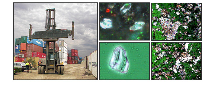
Several years ago research was undertaken to evaluate environmental contamination accessing gearbox breather vents in a then one year-old Plastic Blow Moulding Factory. The plant’s epoxy sealed floor is wet mopped out twice per week therefore when compared to the industrial norm, this is an above average clean factory. This RH image shows one side of the machine layout on the factories blow moulding floor.
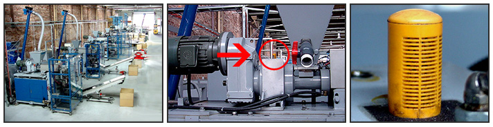
The above images from the same plant is an extruder screw gearbox, note it’s well maintained clean state. The right image is the extruder screw gearbox Breather Vent. The breather filter was removed, washed with super clean solvent and the washing solvent filtered.
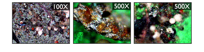
These above images are a general overview @ 100X of the contamination washed out of the gearbox Breather Vent Filter. The other two images indicate the debris @ 500X, it constitutes are plastic particles, fluff, fibres and general dirt and debris.
As enclosed gear cases or transmissions cool down the breather equalisation vent “inhales,” with the in flowing air carrying in any environmental airborne contaminating particles and moisture intermixing in with the internal gear case oil. This captures & holds the airborne contaminates, concentrating them in the lubricating fluid while only releasing the air as the drive re-warms again.
The airborne dirt stays in the oil effectively being concentrated with each thermal cycle until the contamination reaches a level causing “symptoms” that either gets the lubricant replaced by oil change or ignored until ultimately the drive is damaged by “Wearing Out.”
Gearbox and Transmission oil reservoirs are usually filled to 30% to 50% of gear case volume to provide adequate lubrication and control lubricant expansion, foaming and churning.
Experience has indicated if oil samples from plant and equipment are periodically monitored the majority of different modes of abnormal machine wear can be detected and once detected the abnormal wear controlled, the following page’s charts indicate the level of cleanness that frequently encountered machines types are required to be operated at so abnormal wear can be monitored and controlled.
If contamination levels in lubricants are maintained in the below charts green areas plant & equipment life extensions of several times are often achieved. Once very clean to super clean lubricant contamination levels are achieved in plant and equipment the applications life will extend out reducing wear and tear to virtually zero. This chart indicates the level of cleanness required in different lubricating fluids to prevent wear.
 Machinery damage will result if contaminating wear debris & particle levels are permitted to build up into the black, orange or red column levels.
Once these known and proven contaminating particle limits are exceeded completing a Wear Debris Analysis on the sample by microscope will identify the contaminate and once the contaminate is known it usually can be isolated and removed within 2 to 3 maintenance steps. Removing the contaminate and any resulting wear debris allows machinery to return to a normal wear modes. Subsequently maintaining low contamination levels often achieves many times more than normal design life from applications before rebuilding is required.

The same above range code number values accurately apply to the later Laser Particle Counting Techniques.
Lubricant and Plant Monitoring Frequency
Machinery manufacturers will often suggest a lubricant sampling interval but that should only be a rough guideline. The operator is the best judge of sampling intervals and the operator should be asked some pertinent questions in arriving at a sampling interval, such as the following:
What is the failure history?
How costly is a failure? In repair cost? Lost production? Life and safety?
Have operating conditions changed to put additional stress on the machine?
In general, a monthly to quarterly sample interval is appropriate for most important industrial machinery. The answers to the above questions will help decide which regimen is more appropriate. When commencing a new program start with a monthly interval and then extend it as test results and experience allows. The below chart provides a rough guide to commence with, after 2 or 3 test results there should be enough info for these guides to be extended or contracted depending upon the results of analysis.
Basic Testing should include;
ISO Particle Count, Viscosity cSt @ 40°C, Water, Oxidation, PQ, ICP Spectrometer Wear Elements.
(Note WDA by microscope plus water and viscosity replaces all testing below)

As published in Practising Oil Analysis Magazine Link Below
http://www.practicingoilanalysis.com/article_detail.asp?articleid=987&relatedbookgroup=OilAnalysis